06 · Virginia Tech · Design & Economics · Fall 2024
Tech Table
A team-designed portable workspace for students and mobile professionals, developed through customer research, concept selection, CAD, and prototyping.
TeamFour students
ToolsSiemens NX 2312 · Arduino
My contributionsConcepts · Drawings · DFA · BOM
Concept 01 · Individual work
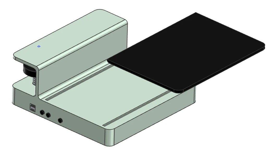
My sliding workspace concept.
A guided surface extends from a compact housing.
TECH TABLE · MOTION STUDYSCROLL TO EXPLORE
SLIDING SURFACECompact configuration
Reconstructed from CAD references · Illustrative geometry
01 / My sliding concept
01 / My sliding concept
A workspace that slides out.
My individual CAD concept.
My early concept puts a dark work surface over a compact housing. Sliding the surface outward creates usable space without unfolding a large panel. The model follows the arrangement in my individual CAD image.
02 / Surface + guide tracks
Guide the movement.
Keep travel aligned.
The paired tracks shown in the CAD image guide the tabletop as it extends. This animation isolates that straight-line movement so the relationship between the surface, guides, and housing is easy to see.
03 / Packaging + support
Keep the mechanism together.
The housing carries more than the tabletop.
The raised side of the housing packages the clamping area, while the lower body includes the control openings. Extending the surface changes its overhang; support, stiffness, and secure attachment would all need evaluation.
04 / From individual concept to selection
An idea to compare.
One concept within a team process.
This was my contribution to concept generation. The team compared alternatives before developing the final hinged design shown next. The sliding model is a visual reconstruction, not a tested load rating or an exact CAD export.
My individual CAD concept · Original Siemens NX concept image.
Concept 02 · Team development
A fold-out surface. A compact assembly.
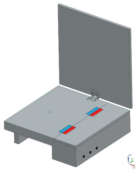
The team’s final design introduces a hinge and an underside clamp.
TECH TABLE · MOTION STUDYSCROLL TO EXPLORE
HINGED SURFACEFolded configuration
Reconstructed from CAD references · Illustrative geometry
01 / The team’s folding concept
01 / The team’s folding concept
Fold small. Open wide.
The team’s final CAD direction.
The final concept replaces the sliding surface with a hinged panel. Folded over the fixed surface, it keeps the assembly compact; opening it extends the workspace. The housing below contains the clamping mechanism.
02 / Controlled fold-out motion
Rotate around one hinge.
Watch the panel unfold.
The moving panel rotates about the edge of the fixed surface. As it passes through the upright position shown in the CAD and prototype photos, the hinge becomes the link between the two tabletop sections.
03 / Look underneath
Attach beneath the surface.
The clamp travels along the housing.
The central screw and two parallel guide rods run along the long axis of the table’s body. The screw advances the clamping plate lengthwise toward the fixed end of the housing, while the guides keep the plate aligned. Actual holding strength depends on the completed mechanism and its attachment.
04 / Intended motion + prototype lessons
Build it. Learn from it.
The physical prototype exposed the next questions.
ABS printing, hinge attachment, wiring, and the motor–battery combination all created practical lessons. The animation explains the intended motion; the prototype and course report document what the team actually built and what still needed improvement.
From CAD to the workshop
The physical prototype.
Team prototype · Retouched top viewTeam prototype · Retouched side view
Photographs retouched to remove temporary rubber bands and background clutter. These remain views of the course prototype; the development findings below are unchanged.
The challenge
Make useful workspace fit where desks don’t.
The project began with customer interviews and surveys to understand the needs of students and mobile professionals working in limited space. The team translated those needs into specifications and compared multiple portable-table concepts.
The resulting design combined a folding tabletop with an underside clamping mechanism. A compact closed form and adjustable attachment were central to the concept.
My contribution
From concepts to drawings and assembly.
My documented responsibilities included project planning, mission-statement reasoning, concept generation and selection, design-for-assembly analysis, final CAD drawings, and shared bill-of-materials work. Every team member also contributed customer research, concepts, and CAD parts.
The team assembled a 13-part model in Siemens NX. I produced the assembly drawing and housing-cover drawing shown in the report. For assembly planning, I used Boothroyd–Dewhurst methods and a learning-curve model.
Team CAD · Hinged panel uprightTeam CAD · Underside mechanism
Team CAD assembly · Siemens NX 2312
13Parts in the CAD assembly
$77.63Course BOM estimate
~5 hoursReported first prototype assembly
Outcome & lessons
The prototype revealed the next design problems.
The physical prototype was made with ABS 3D printing. The report records warping, wiring difficulties, an insufficient hinge adhesive, and a motor–battery mismatch. These are practical findings from building the design.
The $77.63 figure is the course bill-of-materials estimate, not a verified production cost. Similarly, the presentation’s theoretical assembly estimate is distinct from the roughly five hours reported for the first prototype assembly.
Failure modes
Plan for the ways it can fail.
The team’s failure-mode analysis considered loss of clamp grip, tabletop and hinge failure, and motor limitations. These concerns connect the design calculations to real use: holding securely, supporting the working surface, and moving the clamp reliably.
Sources: DP3 Design & Economics report, final video presentation, design portfolio, and LinkedIn project record. Team results and my individual responsibilities are distinguished above.